ENGINE
CYLINDER
c)
d)
e)
Check to be sure the distance from the bot-
tom edge of the crossbar to the top of the
cylinder block is the same on both sides of
the liner.
Check the cylinder liner projection with
tool group (C) at four locations around the
liner.
Liner projection must be 0.033 to 0.175 mm
(.0013 to .0069 in.). Measurements on the
same liner must not be different by more
than 0.05 mm (.002 in.). Average measure-
ments between liners next to each other
must not be different by more than 0.05
mm (.002 in.).
NOTE: If the liner is turned in the bore, it can make
a difference in the liner projection.
4. If the liner projection is not 0.033 to 0.175 mm
(.0013 to .0069 in.), check the thickness of the
following parts: spacer plate, spacer plate gas-
ket and cylinder liner flange. The thickness of
the spacer plate must be 9.970 ± 0.025 mm
(.3925 ± .0010 in.). The thickness of the
spacer plate gasket must be 0.208 ± 0.025 mm
(.0082 ± .0010 in.). The thickness of the cylin-
der liner flange must be 10.282 ± 0.020 mm
(.4048 ± .0008 in.).
NOTE: If the liner projection changes from point to
point around the liner, turn the liner to a new position
in the bore. If the liner projection is still not to
specifications, move the liner to a different bore.
5. When the cylinder projection is correct, put a
mark on the liner and block so the liner can be
installed in the same position from which it was
removed.
NOTE: Cylinder liner projection can be adjusted by
the removal of material from (machining) the con-
tact face of the cylinder block with the use of the
8S3140 Cylinder Block Counterboring Tool Ar-
rangement. Machine to a minimum depth of 0.76
mm (.030 in.) and to a maximum depth of 1.14 mm
(.045 in.). The instructions for the use of the tool
group are in
Special Instruction Form No.
FM055228. Shims are available for the adjustment
of the liner projection. See CYLINDER LINER
PROJECTION in TESTING AND ADJUSTING
for the shim thickness and part number.
6. Remove tooling (B) and (C). Remove the liner.
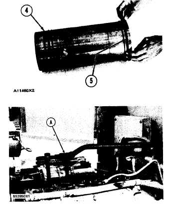
7. Put liquid soap on bottom liner bore in block, on
grooves in lower liner and on O-ring seals (4).
Install O-ring seals on the liner.
8. Put filler band (5) in clean SAE 30 oil for a
moment and install on liner. Install cylinder
liner immediately in the cylinder block (before
TM 5-3805-258-24-2
DISASSEMBLY AND ASSEMBLY
LINERS
9.
10.
Make sure the mark on liner is in alignment
with the mark on the block. Use tooling (A) to
push the liner into position.
Do Steps 5 through 9 for the remainder of the
cylinder liners.
end by:
a) install pistons
expansion of filler band).
5-141