TM 5-3805-262-20
INSTALLATION (SHEET 2 OF 4)
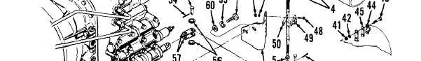
(3) Position cable bracket (61) on rear of transmission; secure using two
washers (60), lock washers (59), and capscrews (58).
( 4)
( 5)
(6)
( 7)
( 8)
( 9)
Position two links (57) on transmission shifting spool and pivot plate
(64); secure using four washers (56), two clevis pins (55) and cotter
pins (54). Bend cotter pins over .
Install clevis (53) on cable assembly (4); thread clevis completely on
cable assembly shaft then tighten nut (5) against clevis.
Route cable assembly (4) between pivot plate (64) and lever (9). Position
clevis (53) on pivot plate and secure using clevis pin (52) and cotter
pin (51). Don’t bend cotter pin until after adjustment procedure is
performed.
Position shim (50) and clamp (49) on cable assembly (4) then position
these parts on cable bracket (61); secure using two capscrews (48), lock
washers (47), and nuts (46).
Position shim (45) and clamp (44) on cable assembly (4) and position
these parts on welded bracket located beneath cab deck near steering
gear; secure using two capscrews (43), lock washers (42), and nuts (41).
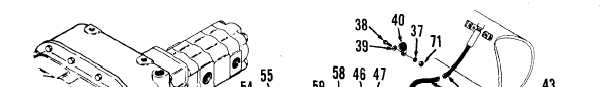
Install clamp (40) on cable assembly (4) and position on welded bracket
located beneath front chassis pivot plate; secure using washer (39),
capscrew (38), lock washer (37), and nut (71).
6-15