TM 5-3805-262-20
ADJUSTMENT (SHEET 2 OF 3)
( 5)
(6)
(7)
( 8)
( 9)
(10)
(11)
(12)
(13)
(14)
(15)
Using pivot plate (9), push shifting spool all the way into control
v a l v e.
Loosen nut (10) on clevis (11) end of cable assembly (12).
Grasp clevis (11) and pull cable all the way out of cable assembly (12)
until cable stops moving .
Turn clevis (11) as required until holes in clevis are aligned with
corresponding hole in pivot plate (9) without moving pivot plate.
Turn clevis (11) one. complete turn counterclockwise.
Connect clevis (11) to pivot plate (9) with clevis pin (8). Don't install
cotter pin (7) now.
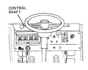
Move control shaft to N (neutral)
p o s i t i o n .
Move control shaft to R (reverse)
position. If control shaft moves
out of R (reverse) position, de-
t e n t i s n o t h o l d i n g s h i f t i n g s p o ol
in place. Remove clevis pin (8).
Turn clevis (11) one complete turn
c o u n t e r c l o c k w i s e ; r e i n s t a l l c l e v is
p i n ( 8 ).
Repeat step (12) above until
control shaft remains in R
( r e v e r s e ) p o s i t i o n.
Install cotter pin (7), bend it over and tighten nut (10) .
Move control shaft to N (neutral) position.
6-19