TM 5-3805-262-34
4-4. FRONT AND REAR AXLES DIFFERENTIAL ASSEMBLY MAlNTENANCE(CONT)
a. Differential Carrier (Cont).
REASSEMBLY (SHEET 5 OF 6)
NOTE
If pinion (23) was replaced, go to step (32) below. Otherwise go to step
(33)
(32)
(a)
(b)
(c)
(d)
(e)
(33)
(34)
(35)
(36)
(37)
(38)
4-230
below.
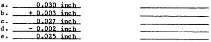
Determine required thickness of shims (13) as follows:
Using micrometer, measure thickness of shims (13) removed during disas-
sembly. Enter on line a below.
Find number written on end of old pinion (23) shaft. First number (025)
is an identification number indicating that pinion and ring gear are a
matched set. Second number and + or - symbol indicate thickness of shims
needed between differential carrier and cage. This number is in
thousandths of an inch. Write the number and the symbol (example: +
0.003) on line b below.
If + symbol is used, subtract number on line b from line a and enter
answer on line c. If - symbol is used, add number on line b to line a
and write answer on line c.
Find number on end of new pinion (23) shaft. Write this number and
symbol on line d below.
If + symbol is used, add line d to line c and write answer on line e. If
- symbol is used, subtract line d from line c and write answer on line
e. Number on line e is required thickness of shims (13).
Apply air drying adhesive (silicon
face on differential carrier (27).
Install correct thickness of shims
Apply air drying adhesive (silicon
rubber gasket) to cage (18) mounting
(13).
rubber gasket) to shims (13).
Install cage (18) and pinion (23) in differential carrier (27).
Install eight washers (12) and capscrews (11). Alternately tighten cap-
screws to 85 to 115 lb-ft.
Install two bearing cups (6) on differential case and gear assembly.