TM 5-3805-262-34
REASSEMBLY (SHEET 6 OF 6)
W A R N I N G
When using chain hoist to remove or install parts, be sure chain hoist
is securely fastened to the part and that all slack in chain is taken
up. Failure to do so could cause serious injury due to the part falling
on you.
If you are injured by falling equipment, obtain medical aid
immediately.
(39) Insert steel bar through differential case and gear assembly. Attach
chain hoist to steel bar and raise and position differential case and
gear assembly over differential carrier (27). SlOWlY lower assembly into
position in differential carrier. Disconnect chain hoist and remove steel
bar.
(40) Install one differential cap (4) with match marks alined.
(41) Install two washers (3) and capscrews (2).
Tighten to 290 to 350 lb-ft.
(42) Install adjusting ring (5).
(43) Position differential cap (4).
(44) Install two washers (3) and capscrews (2). Tighten to 290 to 350 lb-ft.
(45) Install adjusting ring (5).
Do not install two cotter pins
ADJUSTMENT OF DIFFERENTIAL BEARINGS
(1)
(2)
(3)
(4)
(5)
(6)
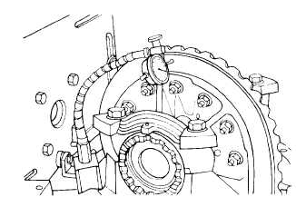
NOTE
(1) until adjustment has been completed.
Install dial indicator against
back side of differential case
and gear assembly ring gear.
Move differential case and gear
assembly back and forth to
check for end play.
If there is no end play, loosen
adjusting ring (5) at back side
of ring gear just enough to ob-
tain end play. Tighten other
adjusting ring (5) just enough
to obtain zero end play.
Rotate ring gear and check runout. If runout exceeds 0.008 inch, remove
differential case and gear assembly (steps (1) through (10), page 4-218)
and check that ring gear is installed correctly and that differential
case halves are properly assembled (page 4-238).
With runout less than 0.008 inch, tighten each adjusting ring (5) one
notch to put correct preload on differential case and gear assembly
bearings.
Adjust ring gear backlash.
4-231