TM 5-3805-262-34
SHEET 5 OF 21
(b) Check if No. 1 cylinder push rods are loose. If push rods are loose, No.
1 cylinder is at TDC on compression stroke: go to step (c) below. If
push rods are tight, crank engine one complete revolution and aline TDC
mark on crankshaft pulley with timing pointer. The No. 1 cylinder is now
at TDC on compression stroke.
(c) Refer to illustration labeled “NO. 1 TDC COMPRESSION STROKE.” Locate
intake and exhaust valves marked by arrows in illustration.
(d) Using tappet adjustment tool and thickness gage, adjust indicated intake
and exhaust valves to the following specifications:
(e)
Tap Pet clearance
Intake valves
Exhaust valves
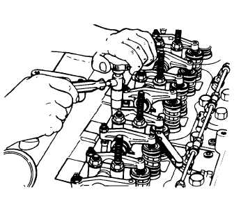
Loosen valve adjusting screw
until proper thickness gage
can be inserted between rocker
arm and valve stem. Then
tighten adjusting screw until
rocker arm-to-valve stem
clearance is correct.
Cold setting
Hot setting
0.015 inch
0.015 inch
0.025 inch
0.020 inch
Crank engine one complete rev-
olution and aline TDC mark on
crankshaft pulley with timing
pointer. No. 6 cylinder is now
at TDC on compression stroke.
3-7


