
TM 5-3805-291-23-1
TROUBLESHOOTING WITH A DIAGNOSTIC CODE - CONTINUED
0009 00
Table 4. Implement Control - Continued.
(MID 082)
MALFUNCTION
TEST OR INSPECTION
CORRECTIVE ACTION
(c) Measure resistance between
1. If resistance that is measured is greater
0967 09 - Continued.
contact J1-31 (wire 121-RD-14) to
than 5,000 Ohms, go to Test 6.
contact J1-10 (wire 944-OR-18)
2. If resistance measured is not greater than
and contact J1-20 (wire 945-BR-
5,000 Ohms for each measurement,
18) on implement ECM.
replace wiring harness in question (WP
0195 00 thru WP 0201 00).
6. Check for an open wiring harness.
(a) Battery disconnect and engine start
switches remain in OFF position
(TM 5-3805-291-10).
(b) All related implement ECMs
remain disconnected from wiring
harness.
(c) Check continuity of data link
circuit in wiring harness.
(d) Perform these measurements:
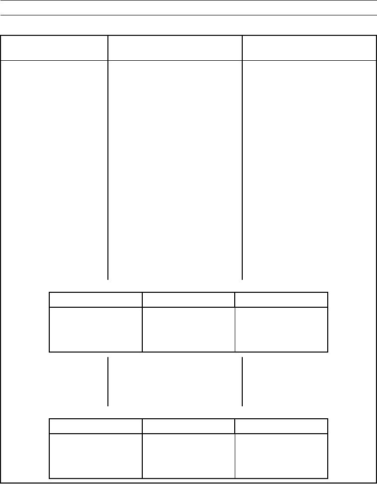
(1) Measure resistance from connec-
tor contact J1-10 (wire 944-OR)
of implement ECM to corre-
sponding connector contacts,
refer to table below.
Module
Contact
Wire
Powertrain ECM
J1-10
944-OR
Messenger
J1-6
944-OR
Engine
J1-8
944-OR
(2) Measure resistance from connec-
tor J1-20 (wire 945-BR) of
implement ECM to correspond-
ing connector contacts, refer to
table below.
Module
Contact
Wire
Powertrain ECM
J1-20
945-OR
Messenger
J1-5
945-OR
Engine
J1-9
945-OR
0009 00-264