• Home
  • Download PDF
  • Order CD-ROM
  • Order in Print
Figure 1. Pin Punch and Roll Pin.
Figure 4. Pin Punch and Roll Pin.

Operators Manual For M400T And M400W
Page Navigation
  97    98    99    100    101  102  103    104    105    106    107  
img
.
TM 5-3805-292-10
0012
CONFIGURATION CONTINUED
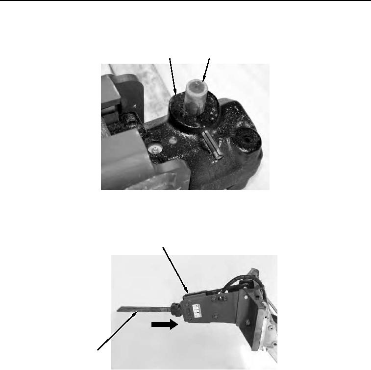
5. Remove retaining pin (Figure 2, Item 2) from housing (Figure 2, Item 1).
1
2
458-0892
Figure 2. Hydraulic Hammer Pins.
0012
6. Insert attachment (Figure 3, Item 2) into housing (Figure 3, Item 1) and align attachment with housing bore.
1
2
458-0066
Figure 3. Installing Attachment on Hydraulic Hammer.
0012
0012-3


Privacy Statement
Press Release
Contact

© Copyright Integrated Publishing, Inc.. All Rights Reserved.