
TM 5-3805-292-10
0012
CONFIGURATION
0012
1. Ensure engine is stopped. Refer to Stopping Engine (WP 0005).
WARNING
Wear eye protection when removing roll pin. Failure to follow this warning may result in
injury to personnel.
NOTE
There are five attachments for the hydraulic hammer. All attach in the same manner.
2. Install hydraulic hammer on machine (WP 0010).
3. Position hammer so attachments can be installed.
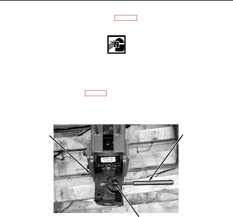
4. Using hammer and pin punch (Figure 1, Item 2), remove roll pin (Figure 1, Item 3) from housing (Figure 1,
Item 1).
2
1
458-0308
3
Figure 1. Pin Punch and Roll Pin.
0012