
TM 5-3805-292-23
0087
INSTALLATION
00087
N OT E
If only seal kit was installed, proceed to step 2.
Tilt cylinder weighs 45 lbs.
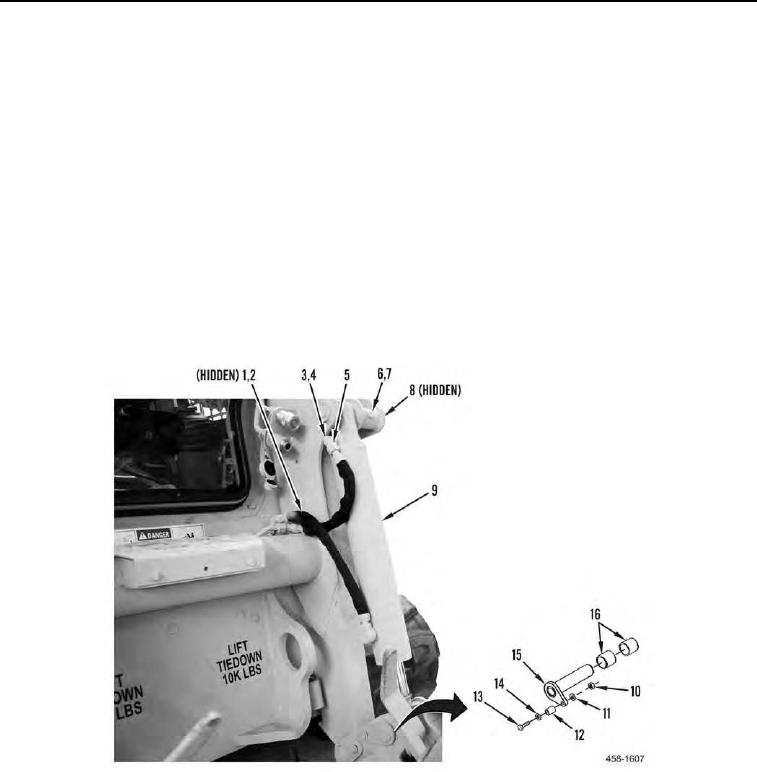
1. Install tilt cylinder (Figure 4, Item 9), pin (Figure 4, Item 8), bolt (Figure 4, Item 7), and nut (Figure 4, Item 6) on
machine.
2. Install spacers (Figure 4, Item 16), pin (Figure 4, Item 15), spacer (Figure 4, Item 12) washer (Figure 4, Item
14), bolt (Figure 4, Item 13), washer (Figure 4, Item 11), and nut (Figure 4, Item 10) on machine.
3. Install nut (Figure 4, Item 4) and elbow (Figure 4, Item 3) on tilt cylinder (Figure 4, Item 9).
N OT E
Install hydraulic hoses and fittings as tagged during removal.
4. Connect two hydraulic hose fittings (Figure 4, Item 5) to hydraulic hoses (Figure 4, Item 1) and two new O-rings
(Figure 4, Item 2) to tilt cylinder (Figure 4, Item 9).
Figure 4. Tilt Cylinder.
0087
END OF TASK
FOLLOW-ON TASKS
00087
Verify correct operation of machine (TM 5-3805-292-10).
END OF TASK
END OF WORK PACKAGE