
TM 5-3805-292-23
0088
INSTALLATION
00088
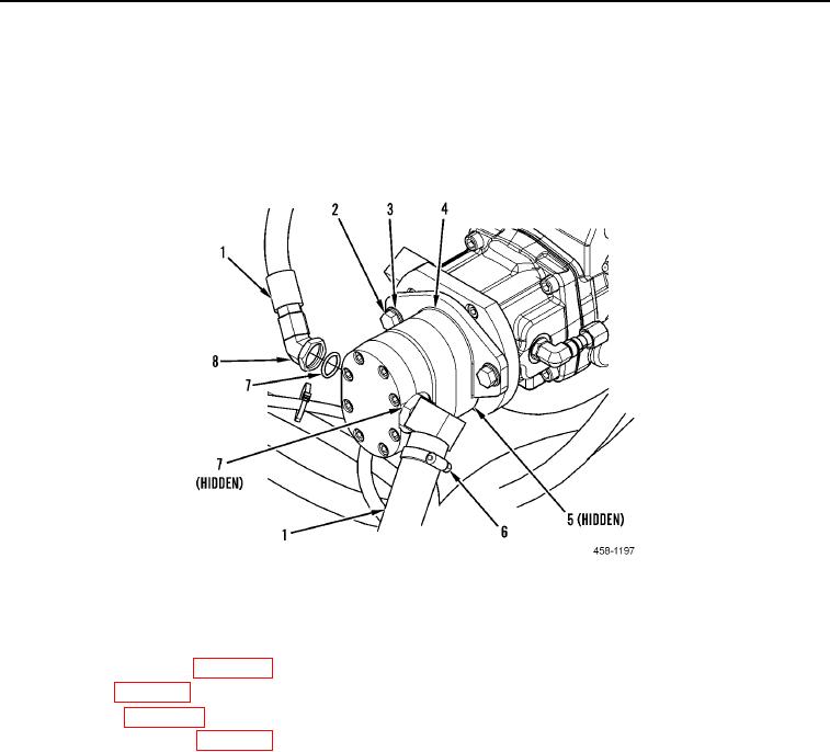
1. Install new O-ring (Figure 4, Item 5) gear pump (Figure 4, Item 4), two washers (Figure 4, Item 3), and bolts
(Figure 4, Item 2) on machine.
2. Install two new O-rings (Figure 4, Item 7) and hydraulic hose fittings (Figure 4, Item 8) on gear pump (Figure 4,
Item 4).
3. Install two hydraulic hoses (Figure 4, Item 1) on hydraulic hose fittings (Figure 4, Item 8).
4. Tighten hose clamp (Figure 4, Item 6).
Figure 4. Gear Pump.
0088
END OF TASK
FOLLOW-ON TASKS
00088
1. Install cab cover plate (WP 0095).
2. Install seat (WP 0126).
3. Close ROPS (WP 0134).
4. Fill hydraulic reservoir (WP 0009).
5. Verify correct operation of machine (TM 5-3805-292-10).
END OF TASK
END OF WORK PACKAGE