
TM 5-3805-298-23-2
0180
INSTALLATION CONTINUED
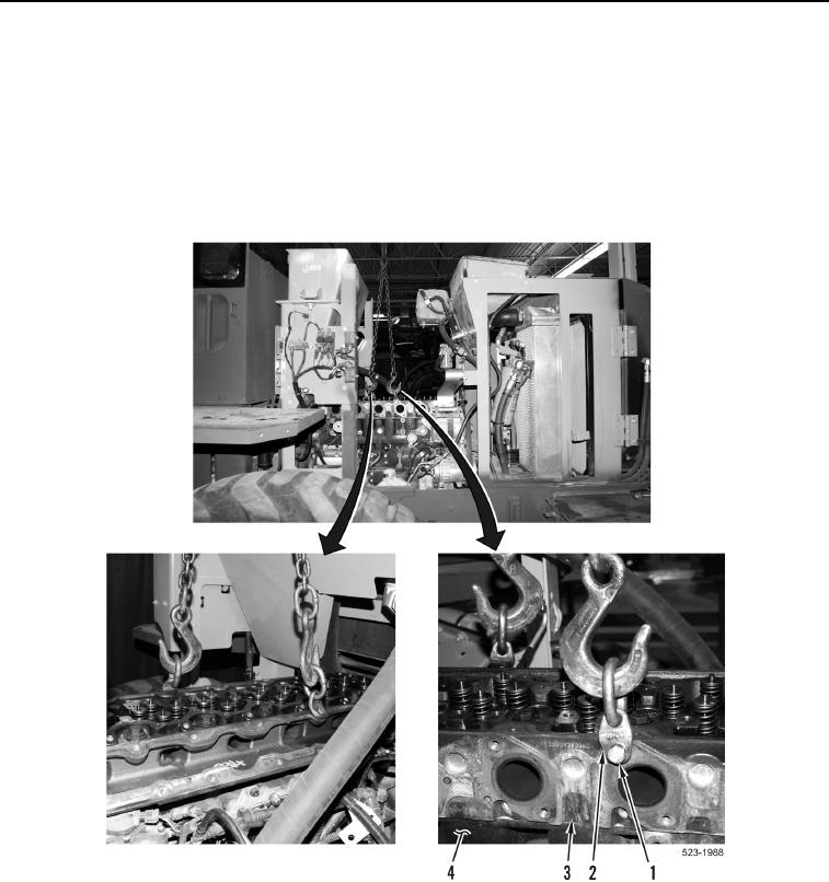
4. Install two bracket links (Figure 13, Item 2) and bolts (Figure 13, Item 1) on cylinder head (Figure 13, Item 4).
5. Install lifting device on bracket links (Figure 13, Item 2).
6. Using lifting device, install cylinder head (Figure 13, Item 3) on cylinder head (Figure 13, Item 4).
7. Remove lifting device from bracket links (Figure 13, Item 2).
8. Remove two bolts (Figure 13, Item 1) and bracket links (Figure 13, Item 2) from cylinder head
(Figure 13, Item 3).
Figure 13. Cylinder Head Lifting Device.
0180