TM 5-3805-258-24-1
F U E L S Y S T E M
T E S T I N G
A N D
A D J U S T I N G
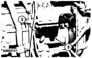
4. Install indicator bracket on the fuel pump
housing. The lever on the bracket assembly
must be in slot (2) on the fuel rack. After the
bracket assembly is tightened to the housing,
the lever must move smoothly when the gover-
nor is moved from low idle to high idle.
I N D I C A T O R B R A C K E T I N S T A L L E D
5. 5P4814 Collet. 6. Indicator bracket.
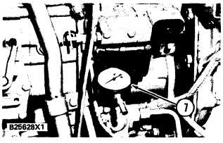
5. Put 9S229 Contact Point on dial indicator
(7). Install dial indicator (7) in collet (5) and
tighten just enough to hold the dial indicator.
D I A L I N D I C A T O R I N S T A L L ED
7. Dial indicator.
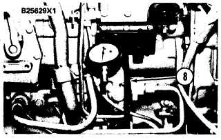
6. Move the governor control lever to the FUEL
OFF position (rotate governor shaft clock-
wise). Install 7N1048 Timing Pin (8) in the
hole in the bracket assembly. Push the timing
pin in until contact is made with the fuel
rack.
7. Move the governor control lever to the HIGH
IDLE position (rotate governor shaft counter-
clockwise) and hold in this position. The fuel
rack will move against the timing pin and stop.
This is the rack zero position. Adjust the revo-
lution counter on the dial indicator to zero.
Tighten collet (5) only enough to hold the in-
dicator in this position. Move the dial of the
indicator to get alignment of the pointer and
zero. Remove the timing pin.
8.
9.
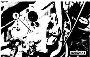
A I R F U E L R A T I O C O N T R O L R E M O V E D
( T Y P I C A L E X A M P L E)
9. Plug.
Remove the air fuel ratio control, shutoff solen-
oid and remove plug (9) from the rear of the
governor housing.
Back out the bolt in compressor (10) five revolu-
tions and install the com-presser in the hole plug
(9) was removed from.
T I M I N G P I N I N S T A L L ED
8. 7N1048 Timing Pin.
C O M P R E S S O R
I N S T A L L E D
( T Y P I C A L E X A M P L E )
4-22
10. 6V2128 Compressor.