
TM 5-3805-291-23-1
TROUBLESHOOTING WITH A DIAGNOSTIC CODE - CONTINUED
0009 00
Table 4. Implement Control - Continued.
(MID 082)
MALFUNCTION
TEST OR INSPECTION
CORRECTIVE ACTION
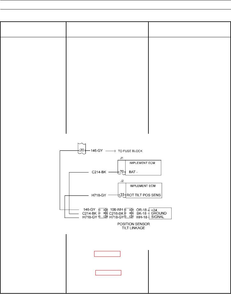
2. Check wiring harness.
0351 08 - Continued.
(a) Sensor remains disconnected from
wiring harness.
(b) Turn battery disconnect switch to
OFF position (TM 5-3805-291-10).
(c) Disconnect wiring harness from
implement ECM (WP 0060 00).
1. If resistance is greater than 5,000 Ohms,
(d) At wiring harness connector for
exit this procedure and repeat this
sensor, measure resistance between
troubleshooting procedure again. If
signal contact C (wire H718-GY)
cause of diagnostic code is not found,
and frame ground.
replace implement ECM (WP 0060 00).
2. If resistance is less than 5,000 Ohms,
replace wiring harness in question (WP
0195 00 thru WP 0201 00).
427-C1653
N OT E
0351 13
Ensure CID 0351 FMI 13 is active and diagnostic code is active.
Connect MSD (WP 0005 00) and check
(a) Calibrate tilt linkage position
sensor (WP 0017 00).
(b) Recheck diagnostic code.
(c) Ensure diagnostic code is active.