
TM 5-3805-292-10
0012
CONFIGURATION CONTINUED
WARNING
Wear eye protection when installing roll pin. Failure to follow this warning may result in
injury to personnel.
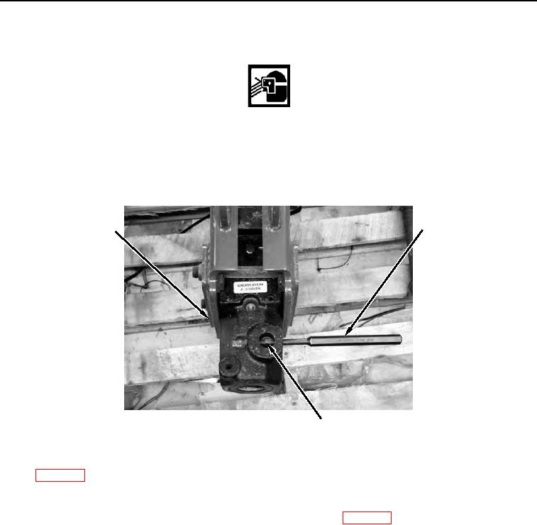
7. Use hammer and pin punch to install retaining pin (Figure 4, Item 2) into housing (Figure 3, Item 1) to hold
attachment (Figure 3, Item 2).
8. Install roll pin (Figure 4, Item 3) into housing (Figure 4, Item 1) to hold retaining pin (Figure 4, Item 2).
2
1
458-0308
3
Figure 4. Pin Punch and Roll Pin.
0012
9. In cold weather, warm hydraulic system of machine before starting hydraulic hammer. Refer to Machine Warm-
up (WP 0005). Circulate hydraulic fluid in system until two bars are displayed on hydraulic fluid temperature
bar graph.
10. With engine at half throttle, activate hydraulic hammer for 5 seconds and stop for 15 seconds. Repeat cycle for
2 to 3 minutes. Refer to Operating Auxiliary Hydraulic Control Pedal (WP 0005).
END OF TASK