
TM 5-3805-292-23
0088
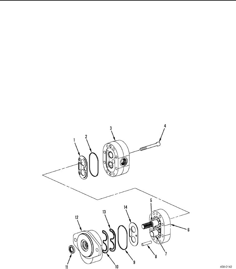
DISASSEMBLY
1. Put identification marks on cover (Figure 2, Item 3), gear plate (Figure 2, Item 6), and cover (Figure 2, Item 12)
for use during assembly.
N OT E
After bolts are removed the gear pump will separate.
2. Remove eight bolts (Figure 2, Item 4) and separate cover (Figure 2, Item 3), gear plate (Figure 2, Item 6), and
cover (Figure 2, Item 12).
3. Remove two dowel pins (Figure 2, Item 8) from gear plate (Figure 2, Item 6).
4. Mark gear teeth that mesh on drive shaft (Figure 2, Item 5) and idler shaft (Figure 2, Item 7) for use during
assembly.
5. Remove drive shaft (Figure 2, Item 5) and idler shaft (Figure 2, Item 7) from gear plate (Figure 2, Item 6).
6. Remove and discard wear plate (Figure 2, Item 1) and seal (Figure 2, Item 2) from cover (Figure 2, Item 3).
7. Remove and discard wear plate (Figure 2, Item 14), seal (Figure 2, Item 9), load seal (Figure 2, Item 13), and
pre-load ring (Figure 2, Item 10) from cover (Figure 2, Item 12).
8. Remove and discard seal (Figure 2, Item 11) from cover (Figure 2, Item 12).
Figure 2. Gear Pump Disassembly.
0088
END OF TASK