
TM 5-3805-298-23-2
0155
Table 1. Kickout System Will Not Operate or Operates Improperly Continued.
0155
MALFUNCTION
TEST OR INSPECTION
CORRECTIVE ACTION
Test Step 34. Test for Shorted Lift
Kickout System Will Not
Kickout Position Sensor.
Operate or Operates
1. Connect connector LE-C3 to lift
Improperly - Continued
kickout position sensor (WP 0012,
Figure 235).
2. Turn battery disconnect switch and
ignition switch to ON position
(TM 5-3805-298-10).
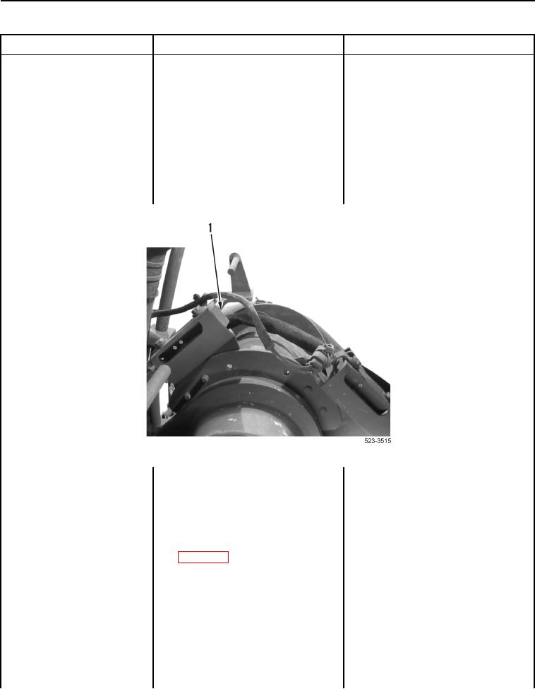
3. Touch magnet to back side of lift
kickout position sensor (Figure 23,
Item 1) and remove magnet.
Figure 23. Lift Kickout Position Sensor.
0155
4. Turn ignition switch and battery
disconnect switch to OFF position
(TM 5-3805-298-10).
5. Remove kickout fuse
(TM 5-3805-298-10).
6. Using digital multimeter
Resistance 5.0 Ohms or Less - Install
(WP 0174), measure resistance
kickout fuse (TM 5-3805-298-10).
between kickout fuse terminals.
Proceed to Test Step 35.
Resistance Greater Than 5.0 Ohms -
Replace lift kickout position sensor
(WP 0297).
Replace kickout fuse
(TM 5-3805-298-10).
Proceed to Test Step 60.