
TM 5-3805-298-23-2
0155
Table 1. Kickout System Will Not Operate or Operates Improperly Continued.
0155
MALFUNCTION
TEST OR INSPECTION
CORRECTIVE ACTION
Resistance 5.0 Ohms or Less - Install
6. Using digital multimeter
Kickout System Will Not
kickout fuse (TM 5-3805-298-10).
(WP 0174), measure resistance
Operate or Operates
between kickout fuse terminals.
Improperly - Continued
Proceed to Test Step 36.
Resistance Greater Than 5.0 Ohms -
Replace bucket kickout position sensor
(WP 0297).
Replace kickout fuse (TM 5-3805-298-
10).
Proceed to Test Step 60.
Test Step 36. Test for Shorted Fork
Kickout Position Sensor.
1. Connect connector N-C3 to fork
kickout position sensor (WP 0012,
Figure 234).
2. Turn battery disconnect switch and
ignition switch to ON position
(TM 5-3805-298-10).
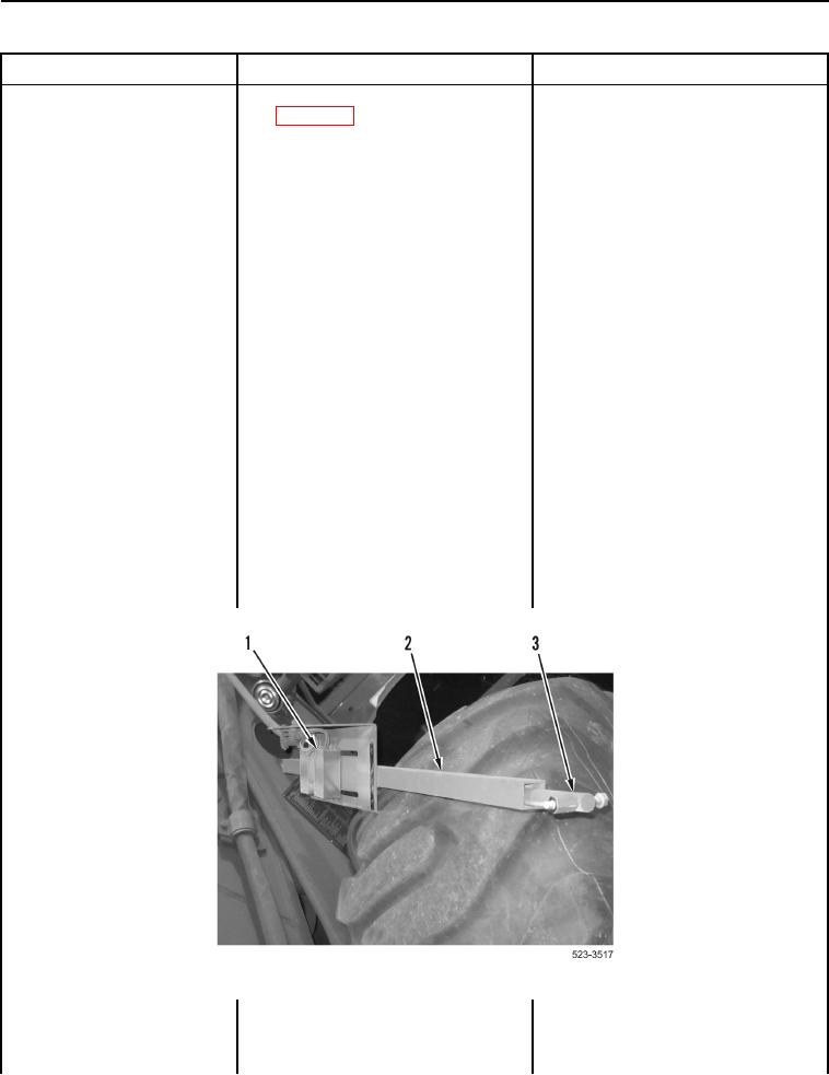
3. Slide shaft (Figure 25, Item 3) into
channel (Figure 25, Item 2) so that
shaft magnet passes over fork
kickout position sensor (Figure 25,
Item 1). Slide shaft out of channel
so that shaft magnet passes over
fork kickout position sensor.
Figure 25. Fork Kickout Position Sensor.
0155