
TM 5-3805-298-23-2
0155
Table 1. Kickout System Will Not Operate or Operates Improperly Continued.
0155
MALFUNCTION
TEST OR INSPECTION
CORRECTIVE ACTION
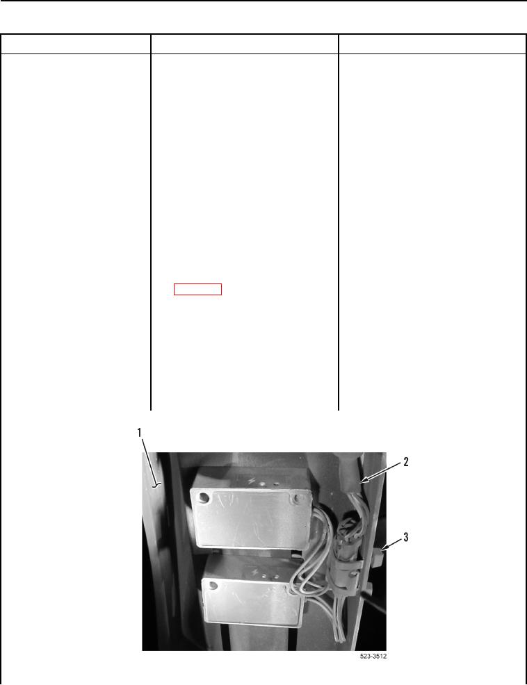
2. Remove two tiedown straps
Kickout System Will Not
(Figure 26, Item 3) from mounting
Operate or Operates
bracket (Figure 26, Item 1) and
Improperly - Continued
wiring harness (Figure 26, Item 2).
Discard tiedown straps.
3. Disconnect connector N-C2 from
bucket kickout position sensor
(WP 0012, Figure 233).
4. Turn battery disconnect switch and
ignition switch to ON position
(TM 5-3805-298-10).
5. Set implement disable switch to
unlock position
(TM 5-3805-298-10).
6. Set kickout switch to ON position
(TM 5-3805-298-10).
7. Using digital multimeter
Voltage 0.5 V or Greater Proceed to
(WP 0174), test for voltage
Test Step 40.
between connector N-C2
Voltage Less Than 0.5 V and Directed
terminal B (WP 0012, Figure 233)
Here From Test Step 8 Replace
and ground.
bucket kickout position sensor
(WP 0297).
Proceed to Test Step 60.
Voltage Less Than 0.5 V and Directed
Here From Test Step 11 Proceed to
Test Step 53.
Figure 26. Tiedown Straps.
0155