
TM 5-3805-298-23-2
0155
Table 1. Kickout System Will Not Operate or Operates Improperly Continued.
0155
MALFUNCTION
TEST OR INSPECTION
CORRECTIVE ACTION
Test Step 35. Test for Shorted Bucket
Kickout System Will Not
Kickout Position Sensor.
Operate or Operates
1. Connect connector N-C2 to bucket
Improperly - Continued
kickout position sensor (WP 0012,
Figure 233).
2. Turn battery disconnect switch and
ignition switch to ON position
(TM 5-3805-298-10).
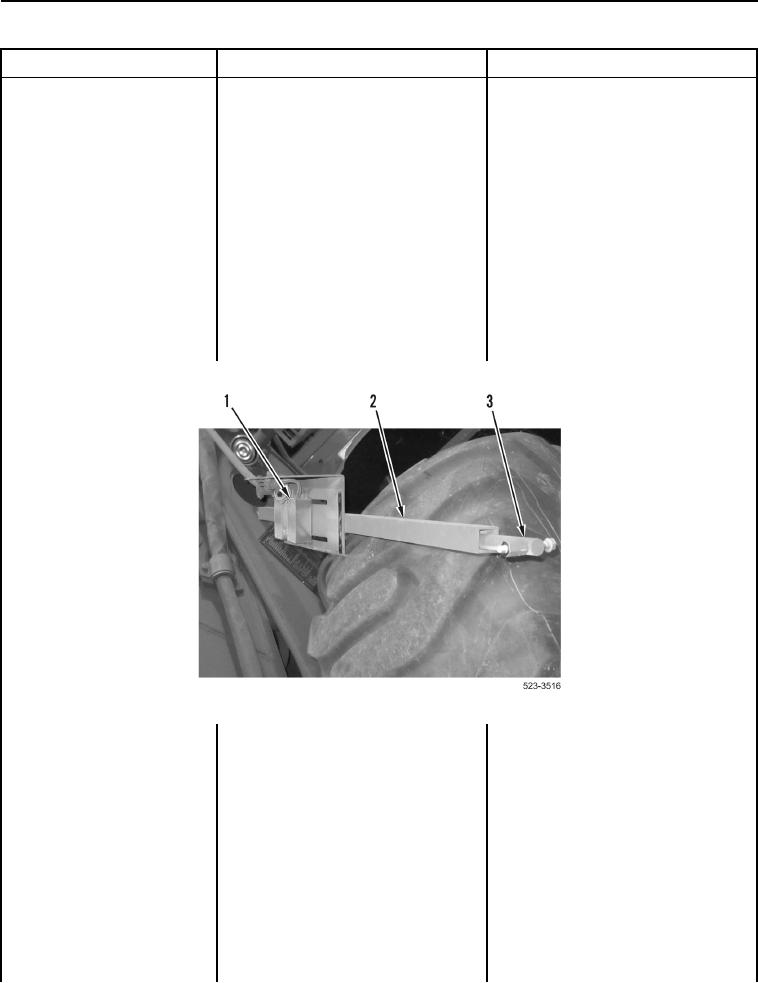
3. Slide shaft (Figure 24, Item 3) into
channel (Figure 24, Item 2) so that
shaft magnet passes over bucket
kickout position sensor (Figure 24,
Item 1). Slide shaft out of channel
so that shaft magnet passes over
bucket kickout position sensor.
Figure 24. Bucket Kickout Position Sensor.
0155
4. Turn ignition switch and battery
disconnect switch to OFF position
(TM 5-3805-298-10).
5. Remove kickout fuse
(TM 5-3805-298-10).