
TM 5-3805-298-23-2
0155
Table 1. Kickout System Will Not Operate or Operates Improperly Continued.
0155
MALFUNCTION
TEST OR INSPECTION
CORRECTIVE ACTION
Kickout System Will Not
Operate or Operates
Improperly - Continued
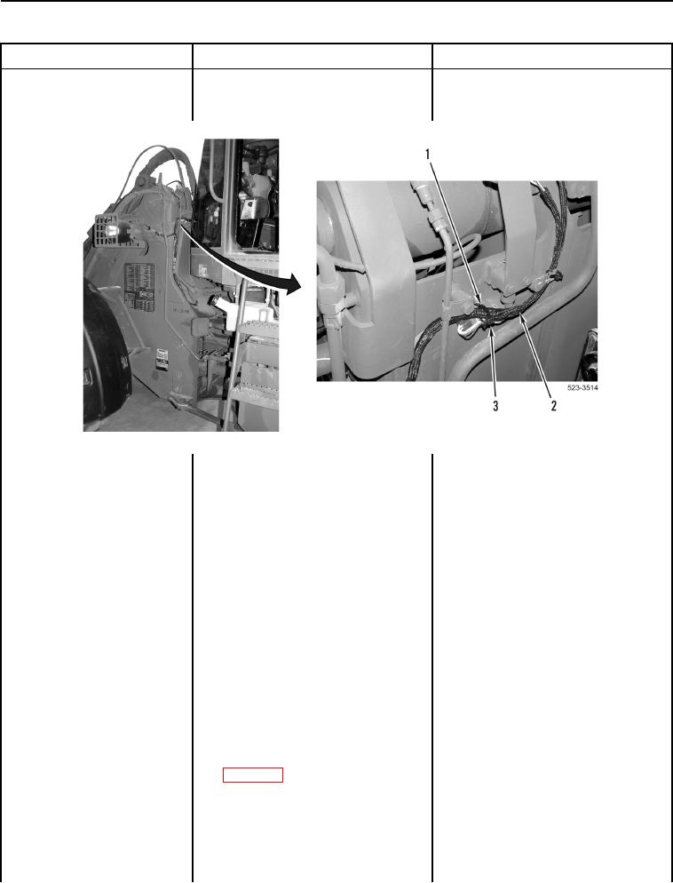
Figure 29. Tiedown Strap.
0155
Test Step 44. Test for Shorted Front
Frame Wiring Harness.
1. Turn ignition switch and battery
disconnect switch to OFF position
(TM 5-3805-298-10).
2. Disconnect connector LE-C1
(WP 0012, Figure 87) from
connector C-C10 (WP 0012,
Figure 86).
3. Turn battery disconnect switch and
ignition switch to ON position
(TM 5-3805-298-10).
4. Set implement disable switch to
unlock position
(TM 5-3805-298-10).
5. Set kickout switch to ON position
(TM 5-3805-298-10).
6. Using digital multimeter
Voltage 0.5 V or Greater Replace
(WP 0174), test for voltage
lower cab wiring harness (WP 0291).
between connector C-C10
Proceed to Test Step 60.
terminal 1 (WP 0012, Figure 86)
Voltage Less Than 0.5 V Replace
and ground.
front frame wiring harness (WP 0301).
Proceed to Test Step 60.