
TM 5-3805-291-23-1
TROUBLESHOOTING WITH A DIAGNOSTIC CODE - CONTINUED
0009 00
Table 4. Implement Control - Continued.
(MID 082)
MALFUNCTION
TEST OR INSPECTION
CORRECTIVE ACTION
427-C1658
N OT E
0356 05
The following test procedure may create other diagnostic codes. Ignore these
created diagnostic codes and clear diagnostic codes when original diagnostic
code is corrected.
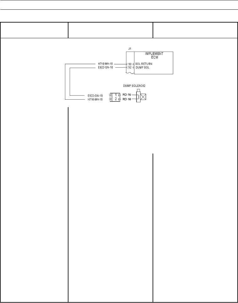
Return lines for solenoids are joined and return lines connect to contact J1-50
(wire H716-WH) of implement ECM.
Ensure diagnostic code indicator is active and diagnostic code is active.
1. Check solenoid.
(a) Turn battery disconnect and engine
start switches to ON position (TM
5-3805-291-10).
(b) Disconnect dump solenoid from
wiring harness (WP 0218 00).
(c) Observe ON/OFF status of
diagnostic code indicator.
(d) At wiring harness connector for
1. If diagnostic code indicator remains
solenoid, place a jumper wire
active, harness or implement ECM has
between contact 2 (wire H716-
failed. Go to Test 2.
WH) and contact 1 (wire E922-
2. If diagnostic code indicator is inactive,
GN).
repeat this test to verify failure. Replace
solenoid (WP 0218 00) or replace wiring
harness in question (WP 0195 00 thru
WP 0201 00). Approximate resistance of
a proportional solenoid valve is from 6 to
12 Ohms.