
TM 5-3805-291-23-1
TROUBLESHOOTING WITH A DIAGNOSTIC CODE - CONTINUED
0009 00
Table 4. Implement Control - Continued.
(MID 082)
MALFUNCTION
TEST OR INSPECTION
CORRECTIVE ACTION
427-C1657
N OT E
0355 05
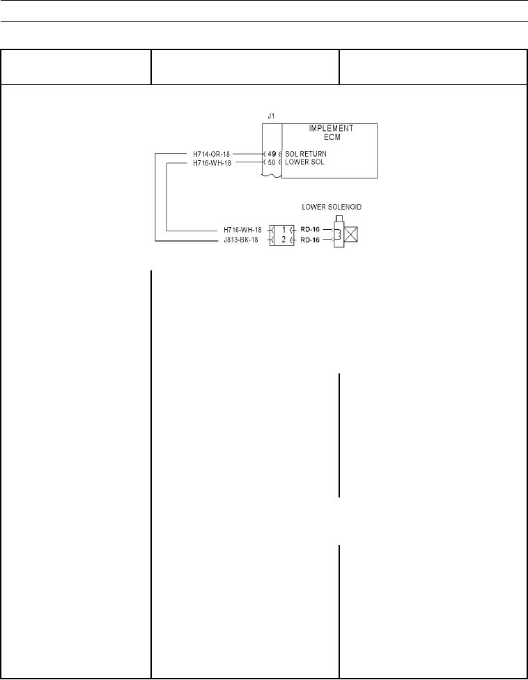
All solenoid return lines for solenoid are joined and return lines are connected to
contact J1-50 (wire H716-WH) of implement ECM.
The following procedure may create other diagnostic codes. Ignore these created
diagnostic codes and clear diagnostic codes when original diagnostic code is cor-
rected.
Ensure diagnostic code is active and diagnostic code indicator is active.
1. Check solenoid.
(a) Turn battery disconnect and engine
start switches to ON position (TM
5-3805-291-10).
(b) Disconnect lower solenoid from
wiring harness (WP 0218 00).
(c) Observe ON/OFF status of
diagnostic code indicator.
N OT E
Approximate resistance of a proportional solenoid valve is from 6 to
12 Ohms.
(d) At wiring harness connector for
1. If diagnostic code indicator remains
solenoid, place a jumper wire
active, go to Test 2.
between contact 1 (wire H714-OR) 2. If diagnostic code indicator is inactive,
and contact 2 (wire H716-WH).
repeat this test to verify failure. Replace
solenoid (WP 0218 00) or wiring harness
in question (WP 0195 00 thru WP 0201
00).