
TM 5-3805-291-23-1
TROUBLESHOOTING WITH A DIAGNOSTIC CODE - CONTINUED
0009 00
Table 4. Implement Control - Continued.
(MID 082)
MALFUNCTION
TEST OR INSPECTION
CORRECTIVE ACTION
427-C1655
1. Check sensor.
0353 08
(a) Observe ON/OFF status of
diagnostic code indicator.
(b) Disconnect wiring harness from
1. If diagnostic code is active, sensor is not
sensor (WP 0219 00).
causing diagnostic code. Go to Test 2.
2. If diagnostic code is inactive, replace
joystick (WP 0219 00).
2. Check wiring harness.
(a) Sensor remains disconnected from
wiring harness.
(b) Turn battery disconnect switch to
OFF position (TM 5-3805-291-10).
(c) Disconnect wiring harness from
implement ECM (WP 0060 00).
1. If resistance is greater than 5,000 Ohms,
(d) At wiring harness connector for
exit this procedure and repeat this
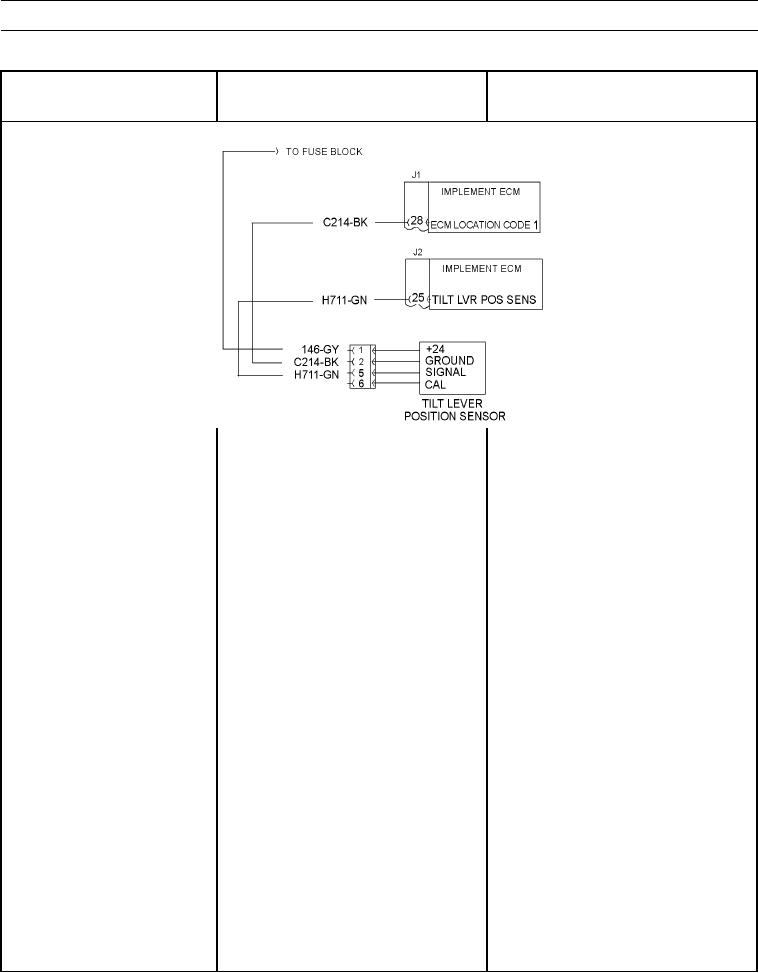
sensor, measure resistance between
troubleshooting procedure. If diagnostic
signal contact 3 (wire H711-GN)
code is not found, replace implement
and ground.
ECM (WP 0060 00).
2. If resistance is less than 5,000 Ohms,
replace wiring harness.
3. Check sensor output.
(a) Reconnect wiring harness
connectors to implement ECM.
Reconnect wiring harness
connector to sensor.